![]()
![]()
![]()
![]()
![]()
")
")
![]()
Yves GARY Affichages : 21546
Catégorie : CONSTITUTION
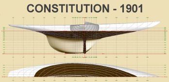 Pour le défi de 1901, Herreshoff a encore été choisi et en s'appuyant sur le dernier défenseur réalisé, il a commencé à dessiner un bateau qui devait être encore plus rapide que Columbia.
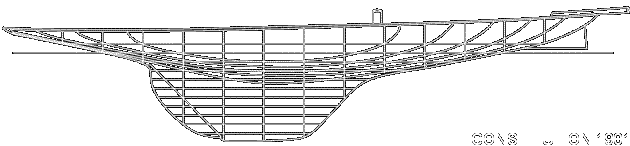
Constitution, c'est le nom du nouveau bateau, a montré de nombreuses différences dans sa construction par rapport aux defenders précédents, si ce n'est dans sa forme ou dans son type.
Une nouvelle structure du squelette a été utilisée qui, bien que plus chère, a donné une construction plus légère, avec, disait-on, la même résistance. Les membrures ont été placées à environ six pieds de distance au lieu de la distance ordinaire d'environ un pied et demi. Le bordé est en bronze, 3/16 de pouce d'épaisseur pour les superstructures et 7/32 en dessous comme dans les deux ou trois derniers défenseurs. Le pont était mince en acier recouvert de carreaux de liège collés sous pression. La finition était de la plus haute importance.
Semblable à Columbia en de nombreux points, en particulier au-dessus de l'eau, Herreshoff est revenu au tracé de Defender pour les œuvres vives, le couple au maître bau étant assez similaire à celui du yacht de 1895.
|
 |
||||||||||||||||||||||||||||||||||||||||||||||||||


Télécharger les PLANS POUR DELFTSHIP : Fichier Delftship à terminer et images de fond d'écran


W. P. Stephens, un architecte, a donné la description suivante de la construction de Constitution dans le numero de Juin 1901 de The Rudder :

"The framing of the hull follows an entirely new method, as applied to yacht construction, the invention of Mr. Herreshoff. In all ordinary metal construction the general plan of the framing is similar to the skeleton of a fish, there being a backbone or keel with a large number of ribs or frames, all practically of the same size, attached to it at regular intervals. In the case of the previous Herreshoff ninety-footers the frames have been of steel angles, extending from keel to deck, and spaced about twenty inches apart. A few longitudinal members in the form of bilge-stringers are used to stiffen the steel frames. Other angles run along the inside of them, but the main strength of the construction rests in the frames and the plating, the ribs and the skin.
 "The framing of the hull follows an entirely new method, as applied to yacht construction, the invention of Mr. Herreshoff. In all ordinary metal construction the general plan of the framing is similar to the skeleton of a fish, there being a backbone or keel with a large number of ribs or frames, all practically of the same size, attached to it at regular intervals. In the case of the previous Herreshoff ninety-footers the frames have been of steel angles, extending from keel to deck, and spaced about twenty inches apart. A few longitudinal members in the form of bilge-stringers are used to stiffen the steel frames. Other angles run along the inside of them, but the main strength of the construction rests in the frames and the plating, the ribs and the skin.
"In Constitution the frames play a subordinate part, only one-quarter of them extending above the hollow of the floor, at the joint of the fourth plate from the top and the third from the bottom. In place of them a system of web frames is used, the web frame being practically a solid bulkhead with the central portion cut out, leaving a rim of about fifteen inches width in the midship webs and decreasing toward the ends.
"The construction is similar to that used in model yachts, in which each section is cut from a solid piece of wood, the centre being removed to lighten it. These web frames are built up of sheet steel from 5/40 to 6/40-inch thick and fifteen inches wide, in sections joined by a 2 1/2-inch lap joint. Both outer and inner edges are stiffened by a pair of steel angles, one and one-half by one and one-half inches, the outer angles, which are cut at each longitudinal, serving to connect the web frame to the plating. The web and angles are continuous under the deck. These web frames are spaced at four times the usual distance apart, eighty inches, and between them are three ordinary frames at twenty-inch intervals, but extending only up to the hollow of the floor. Above this point the web frames are connected by a system of longitudinal running through them and directly in contact with the hull plating.
"There are seven plates, each about four feet wide, on each side of the vessel, of Tobin bronze, the lower or garboard being 8/32-inch thick, the next three each 7/32-inch, and the three on the topsides each 6/32-inch. The garboard laps for about half of its width on to the lead keel, to which it is fastened by bronze tap screws, each five-eighths by six inches, there being four hundred and twelve screws to each garboard.
"The keel-plate is made up of three sections of bronze casting, as in Defender and Columbia, twenty inches wide and about one-half inch thick, with a flange four inches high along each edge to which the centre of the garboard is riveted ; similar thwart ship flanges being cast for the heels of the frames and the floor-plates. The keel-plate is also fastened directly to the lead keel by bronze lag screws one by ten inches, and thirty-seven in number. The second plate from the bottom laps over the upper edge of the garboard in the usual way and also over the lower edge of the third plate, but the adjoining edges of the third and fourth plates form a flush joint, both butting on the head of the T-beam which forms the longitudinal at this point.
"The next longitudinal, going upward, is in the middle of the fourth plate, a bulb-angle, and they continue alternately, a T-beam at each joint and a bulb-angle in the center of each plate, the last one being a bulb-angle on top of the deck plating connecting it to the upper strake, which extends about two inches above the deck. The T-bars are four and one-half by four and one-half inches in the middle of the hull, diminishing in size at the ends, and the bulb-angles are three by two inches in the middle. The former are joined by means of a U-shaped clip, the ends butting, but the latter are laid back to back and lap at the joints, the ends being riveted together.
"All the longitudinals are continuous from stem to horn-timber, thus passing through the web frames. A system of braces, of 1^-inch steel tubing is used, two at each intersection of web frame and longitudinal, bracing the inner edge of the web and preventing it from buckling.
"The deck is of steel plate supported by longitudinal stringers of bulb-angles, passing through the upper edge of each web frame. The ordinary deep floor-plates at the heels of the frames have been replaced by smaller ones only twelve inches deep on each of the short angle-frames with a tie twelve inches by 1/4-inch higher up and a short brace 1 3/4-inch square between the two, thus stiffening the interior of the fin between the web frames. Each web frame is stiffened by two struts of three-inch steel tubing from the bilge to the deck, at about the quarter breadth of the boat, but near the mast these tubes are moved in close to the step and partners, and additional ones, placed diagonally in a fore and aft direction, are used.
"The mast step itself is very strongly built, an extra web frame is inserted, and the keel-plate is increased to 5/8-inch thickness beneath the step. The throats of the web frames under the mast are deepened and the keel is built up into a deep longitudinal girder for a length of twenty feet, the top of this structure being nearly seven feet below the deck. The mast rests on two thicknesses of 5/8-inch steel plate riveted to the web frames and keel-plates ; on the lower end of the mast is a ring of one and one-half by one and one-half inch angle-bar, the vertical flange riveted to the mast and the horizontal flange pierced with holes for 1/2-inch bolts. When the mast is stepped it is bolted fast by this ring to the pedestal, of which it becomes a part, being rooted in the hull by a broad spreading base exactly as a tree is rooted in the soil. The tremendous pressure of the mast, which nearly caused a wreck in Defender in her first races in 1895, is thus transmitted to the whole hull and fin instead of being concentrated in a comparatively small area."


